Thermal Systems Design Center Thermally activated heating, cooling and dehumidification technologies will become an essential tool for efficient use of all forms of fossil energy. Watch this space for important information on engineering tools to help recycle energy. |
||||
Integrated CHP Systems Corp. 50 Washington RdPrinceton Junction, NJ 08550 Phone: (609) 799-2340
|
||||
 |
|
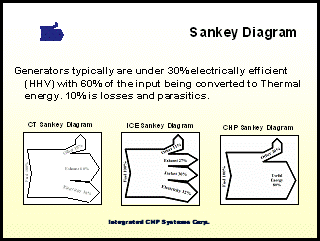
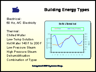
Download CHP Thermal Recovery Presentation Combined Heat and Power of Cooling, Heating and Power systems: Introduction: Energy as expressed in Btu’s provides a convenient way to measure heat and electric energy. Electric energy is converted on the basis of one Watt equals 3.414 Btu. By this calculation, on-site electric generators typically produce considerably more heat energy – approximately twice, than electric energy. This heat energy can be applied to a building for heating or converted to cooling energy with thermally activated cooling technologies including chillers, desiccants and absorbers. ‘A Generator is a 60% Efficient Boiler with Free Electricity’ Since the heat energy of the CHP system is the largest single output, its recovery and application will determine the performance of the system. Heat recovery is directly proportional to engine heat output quality (or temperature). Heat output is in the form of exhaust energy for combustion turbines and is split between jacket coolant temperature rise and exhaust energy for internal combustion engines. Heat recovery devices such as heat exchangers and steam generators are used to recover the waste energy into a useable form. Generator engines vary in amount of waste heat recovered (Heat Recovery Efficiency) from a high of close to 90% for non-recuperated combustion turbines to 50% for ‘low-temp’ recuperated microturbines. IC engine heat recovery efficiency typically varies from 60% to 80% when both jacket and exhaust energy are recovered. For applications where the exhaust only is recovered the heat recovery efficiency generally varies from 30% to 40%. T Thermally activated chillers are employed to provide cooling energy typically in the form of chilled water. Steam turbine centrifugal chillers as well as single and double effect absorption chillers take the heat recovered from the engine and convert it to chiller water. Liquid and solid desiccants dehumidify the air using the waste heat to regenerate the system. Steam turbine chillers have the highest efficiency (120%) followed by double effect and single effect absorption with desiccants at the lowest efficiency of around 50%. Thermal Design Approach: Building thermal energy forms vary considerable while electric energy is alternating current at 60 Hz for the vast majority of applications. Thermal design considers the forms and centralization of thermal energy as a primary factor when selecting CHP equipment. Thermal forms are selected to assure a high system load factor. The specification of the op Thermal Electric Ratio (T/E): Once the building’s electric, heating and cooling needs are assessed the Thermal-Electric ratio (thermal energy divided by electric energy) can be calculated. The cooling T/E is expressed in tons per kW and will provide information on the heat recovery efficiency as well as thermal technology efficiency suited to the application. The heating T/E is expressed in MBH/kW and will help identify the most suitable type of heat recovery device as well as the heat recovery efficiency. Once the cooling and heating T/E have been identified then the proper CHP system for maximum load factor can be selected. The following table outlines the primary thermal and electric characteristics for a variety of typical CHP configurations. Values are averages based on a study of 42 engines. Turbine based CHP systems generally have a higher T/E ratio than IC engine based systems. Heat recovery efficiency is high for non-recuperated combustion turbines and IC engine/1E Absorption systems. Efficiency Calculations: Ratings for the generator are based on ISO conditions and ratings for the chillers are based on ARI conditions. The following are the formulae used to calculate the values in the above table: Thermal-Electric Ratio = Chiller Output in Tons / Net Busbar Electric Output. CHP Output Efficiency = (Busbar Output in MBH + Chiller Output in MBH) / Fuel Input HHV Heat Recovery Efficiency = Total Heat Recovered / (Fuel Input LHV – Nom Electric Output in MBH) Nominal Electric Efficiency = Nominal Electric Output in MBH / Fuel Input LHV The Thermal-Electric Ratio (T/E) defines the output characteristic of the CHP system. A proper match between the CHP system and building’s base T/E will assure a high load factor. CHP Output Efficiency is a measure of combined chiller and generator efficiency. Highly ranked systems offer high efficiency electric generation combined with high quality heat output. Low efficient generators with low temperature exhaust or low temperature coolant score poorly by this measure. The CHP Output Efficiency is calculated using the higher heating value (HHV) of fuel. The Heat Recovery Efficiency is a measure of the quantity of heat recovered for useful purpose against the total lower heating value of fuel not converted to electricity. It is an indication of the quality of the heat produced by the engine against its use. The Nominal Electric Efficiency is a common generator industry calculation based on the LHV of fuel. It is usually based on ISO conditions and should be rated for continuous operation at full load. Annual Efficiency: The annual load factor is the amount of thermal and electric energy used by the building divided by the system output calculated using 8,760 hours at full load. It is dependant on the CHP system capacity and efficiency as well as building load. Selection of a system based on thermal-electric ratio will lead to the highest load factor. The following calculations illustrate the effect of the buildings thermal electric ratio on load factor and annual efficiency. Two systems are contrasted – CHP1 is a combustion turbine with two effect absorption chiller and CHP2 is an IC engine with single effect absorption chiller. While CHP1 has a nominal efficiency 17% higher than CHP2 they both have the same annual efficiency when applied to building A. The higher thermal-electric ratio in building B allows for the additional thermal energy available from CHP1 to be utilized, giving it a higher annual output efficiency than CHP2. System Outline: CHP1 = 0.6 Tons/kW Fuel Input = 12.2 MBH/kW (28% Electric Efficiency HHV) CHP2 = 0.3 Tons/kW Fuel Input = 10.5 MBH/kW (34% Electric Efficiency HHV) Nominal CHP1 Output Efficiency = (1 kW + 0.6 Tons) / 12.2 MBH = (3.414 + 7.2) /12.2 = 87% Nominal CHP2 Output Efficiency = (1 kW + 0.3 Tons) / 12.2 MBH = (3.414 + 3.6) / 10.0 = 70% Building A T/E = 0.3 Tons/kW: CHP1 Thermal Load Factor = (Base + EFLH) / Peak = (0.3 + 0.3 x 40%) / 0.6 = 0.42 / 0.6 = 70% CHP2 Thermal Load Factor = 100% CHP1 Output Efficiency = (1 kW + 0.6 Tons x 70%) / 12.2 MBH = (3.414 + 5.04) / 12.2 = 69% CHP2 Output Efficiency = (1 kW + 0.3 Tons x 100%) / 10.0 MBH = (3.414 + 3.6) / 10.0 = 70% Building B T/E = 0.6 Tons/kW: CHP1 and CHP2 Thermal Load Factor = 100% CHP1 Output Efficiency = (1 kW + 0.6 Tons x 100%) / 12.2 MBH = (3.414 + 7.2) / 12.2 = 87% CHP2 Output Efficiency = (1 kW + 0.3 Tons x 100%) / 10.0 MBH = (3.414 + 3.6) / 10.0 = 70%
|
||||
home | services | products | market research | about us | contact us |

 hese es
